Joined: Aug 2017 Posts: 559 Threads: 89
Reputation:
7
Location: Deepest darkest Kent
Danny,
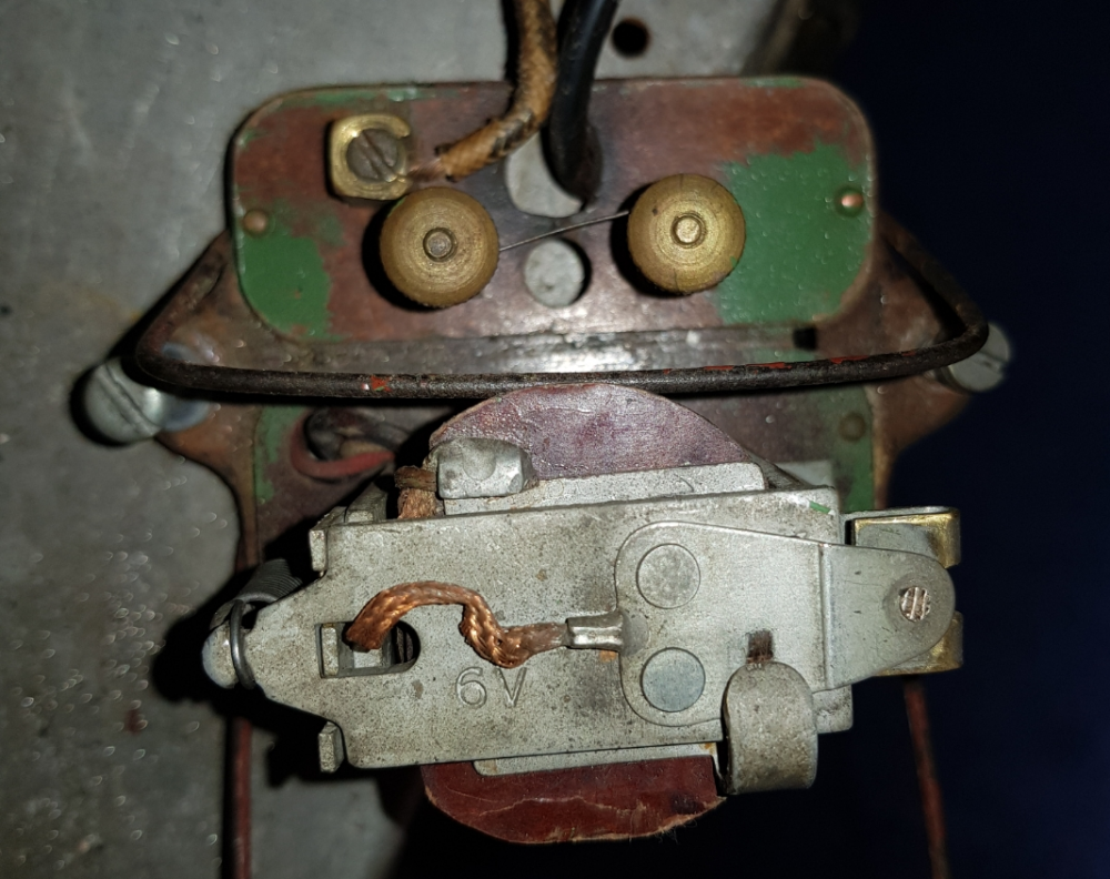
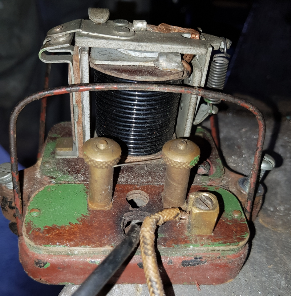
welcome to the forum. Your cutout looks like a CF1 that is missing a terminal.
Photo below of the same type of cutout modified to take a voltage regulator.
If you remove the paint around the base it should be marked with the model number and voltage.
https://flic.kr/p/rmpzN2
Joined: Aug 2017 Posts: 20 Threads: 7
Reputation:
0
Thanks for this Robert - i'll have a go at removing some paint and see if I can find any model numbers.
There's 6V stamped on the top of the cut out (and its currently installed on a 6v car).
I'm going to be keeping the 6v with the re-wire  it all works ok but some of the cables are a bit dubious *cough cough* speaker wire.
Do you know if you can (or if its worth) getting a 6v Voltage Regulator?
Cheers again for your help,
Danny
Joined: Aug 2017 Posts: 2,748 Threads: 31
Reputation:
95
Location: Auckland, NZ
My stock observation for those venturing into Seven electrics...there are few circuit diagrams which show internal connections so very simple systems are rendered unnecessarily obscure, esp where parts are mixed. The Cornwall club article A Charging Refresher covers the 5 basic charging circuits with details of the cutout internals. And particularly for later cars Dorset Club John Cornforths diagram will also likely prove helpful.
A search of the old site will reveal vast info about regulators mechanical and electronic, often mixed with and complicated by 12v conversion. For unmodified dynamos a mechanical 6v regulator used with a the 3rd brush appears promising but it has been claimed that the switching action taxes the brush and rattles the timing gears.
For typical running today charging in the car can be kept modest and a regulated bench charger relied on for maintenance.
Joined: Aug 2017 Posts: 1,716 Threads: 47
Reputation:
25
Location: Auckland NZ
Car type: 36 Nippy, 31 RM, 38 Special, 24 Works Rep
13-09-2017, 09:23 PM
(This post was last modified: 13-09-2017, 09:25 PM by Ian Williams.)
Welcome to the forum Danny, stick with the 6v system you have, just wire it up correctly and all will be well, I am assuming you have the correct switch panel?
Black Art Enthusiast
Joined: Aug 2017 Posts: 20 Threads: 7
Reputation:
0
Thanks for the guidance Bob, I will pull up the "A charging refresher" document and have a look now I have more of an idea what cut out that I have.
I've have made a diagram of the current wiring to use as a reference, I'm in the process of converting this to a circuit diagram for use at a later date (my scribbles on my pad aren't brilliant).
I also found a Ruby Wiring diagram by John Comforth which is drawn in the style of a modern circuit diagram rather than the original diagrams I've seen which I think will be useful. Although I'm not sure which site this came from originally (found it on an internet search a while ago).
Ian, I have the following switch panel. Again any information you can provide on this would be greatly received.

I've just pulled the dashboard forward to make my diagrams and found this lovely tangle of wires 

So far I'm loving the Austin 7 experience, when I received the car it had a broken half shaft and differential was in pieces so that's all been replaced and is now back on the car. I've also rebuilt the hydraulic brakes. I'm not sure my other half would say the same, she's become a garage widow!
Thanks again for any help received 
Joined: Aug 2017 Posts: 559 Threads: 89
Reputation:
7
Location: Deepest darkest Kent
(13-09-2017, 10:11 PM)dannyteal1990 Wrote: Thanks for the guidance Bob, I will pull up the "A charging refresher" document and have a look now I have more of an idea what cut out that I have.
I've have made a diagram of the current wiring to use as a reference, I'm in the process of converting this to a circuit diagram for use at a later date (my scribbles on my pad aren't brilliant).
I also found a Ruby Wiring diagram by John Comforth which is drawn in the style of a modern circuit diagram rather than the original diagrams I've seen which I think will be useful. Although I'm not sure which site this came from originally (found it on an internet search a while ago).
Ian, I have the following switch panel. Again any information you can provide on this would be greatly received.
I've just pulled the dashboard forward to make my diagrams and found this lovely tangle of wires 
So far I'm loving the Austin 7 experience, when I received the car it had a broken half shaft and differential was in pieces so that's all been replaced and is now back on the car. I've also rebuilt the hydraulic brakes. I'm not sure my other half would say the same, she's become a garage widow!
Thanks again for any help received 
As Ian suggests,
stay with 6v. You can use the wiring diagram from a handbook from 1930/1931 which makes it easy follow. Copies of these are available from various sources.
Joined: Aug 2017 Posts: 27 Threads: 6
Reputation:
0
(13-09-2017, 10:28 PM)After 40+ years of driving my 1927 chummy rather briskly and a 1925 12/4 (to which I fitted an overdrive so now cruise at at thrilling speed) both with a beautifuly simple charging systems I confirm that if you follow Ian\s advice you won't go wrong. I dimly remeber some old advice along the lines of about 6 miles of driving pokes back what was taken out of the battery when starting the car, then in the case of my cars turn off the dynamo (don't have half charge). I've never been let down by this. The real issue is drain on the system when using lights but again I haven't found it to be an issue. A simple solution to that problem looks like substiuting bulbs with Leds - some of my friends have done this so that they can use their lights in daytime to improve visibility to oncoming traffic - I prefer the thrill of living dangerously! Wrote: Robert Foreman
(13-09-2017, 10:11 PM)dannyteal1990 Wrote: Thanks for the guidance Bob, I will pull up the "A charging refresher" document and have a look now I have more of an idea what cut out that I have.
I've have made a diagram of the current wiring to use as a reference, I'm in the process of converting this to a circuit diagram for use at a later date (my scribbles on my pad aren't brilliant).
I also found a Ruby Wiring diagram by John Comforth which is drawn in the style of a modern circuit diagram rather than the original diagrams I've seen which I think will be useful. Although I'm not sure which site this came from originally (found it on an internet search a while ago).
Ian, I have the following switch panel. Again any information you can provide on this would be greatly received.
I've just pulled the dashboard forward to make my diagrams and found this lovely tangle of wires 
So far I'm loving the Austin 7 experience, when I received the car it had a broken half shaft and differential was in pieces so that's all been replaced and is now back on the car. I've also rebuilt the hydraulic brakes. I'm not sure my other half would say the same, she's become a garage widow!
Thanks again for any help received 
As Ian suggests,
stay with 6v. You can use the wiring diagram from a handbook from 1930/1931 which makes it easy follow. Copies of these are available from various sources.
Joined: Aug 2017 Posts: 1,790 Threads: 43
Reputation:
15
Location: Malvern, Victoria, Australia
14-09-2017, 07:04 AM
(This post was last modified: 14-09-2017, 07:09 AM by Tony Press.)
Your Cutout and fuse box is as noted a Lucas CF1 - it will be marked with something like 6VER 9 28 on the face below the fuse.
This is earthed through the base so needs all paint removed and if mounted on a wooden board have an earth wire fitted.
The missing 'A' terminal looks to have been replaced with a connector underneath wired up to the cutout coil. The 'D' terminal which is still in place connects through the fuse to the cutout switch.
If you have the original CAV Lucas DEL Dynamo with two terminals +D and SH, the summer/winter charging rate is via a built in resistance in the field windings - connecting the D and SH terminals shorts this resistance out and produces full charge.
As you know this is a third brush dynamo where the final full charge rate is set by moving the third brush.
The switchboard you picture is a Lucas SM5 which is be correct for the DFL and CF1 combination, but the extra switch could indicate the SM5, which incorporates a summer/winter charge setting, is not working properly.
The rats nest of wired behind your SM5 should be removed and a new set of wiring installed as you suggest. Don't refer to the later wiring diagrams - look at the simple 1929 wiring diagram in the Handbook.
Have a look at Handbook 619c http://archive.a7ca.org/wp-content/uploa...7_619C.pdf page 36.
Cheers, Tony.
Joined: Aug 2017 Posts: 1,024 Threads: 6
Reputation:
12
Location: Scottish Borders
The diagram in the handbook incorrectly shows the horn switch before the horn. It should be after the horn and the horn button earths the circuit at the column.
I have a 1929 parts list, publication 670 and pasted in the back is a larger diagram.
This appears to be a Lucas drawing, No W125 and refers to Austin 7 1930/31.

Jim
|

 SmartSelectImage_2017-09-13-15-08-16.png (Size: 1.15 MB / Downloads: 806)


 SmartSelectImage_2017-09-13-15-08-16.png (Size: 1.15 MB / Downloads: 806)


 it all works ok but some of the cables are a bit dubious *cough cough* speaker wire.