The following warnings occurred:
Warning [2] Undefined variable $search_thread - Line: 60 - File: showthread.php(1617) : eval()'d code PHP 8.1.31 (Linux)
File Line Function
/inc/class_error.php 153 errorHandler->error
/showthread.php(1617) : eval()'d code 60 errorHandler->error_callback
/showthread.php 1617 eval


Thread Rating:
  • 1 Vote(s) - 5 Average
  • 1
  • 2
  • 3
  • 4
  • 5
Lucas C35A Regulator
#11
(27-03-2023, 02:05 PM)Lowbarn Wrote: The ammeter shows no charge Stuart.
Richard.

So the the 9V you were seeing on the 'D' terminal earlier in this thread isn't there when the dynamo is connected. Have you tried 'flashing' the F terminal with a positive lead yet? If the dynamo has lost its residual magnetism it won't charge even if everything else is good.
Reply
#12
Yes I did see 9v at the D terminal of the Dynamo last Friday.
Saturday, with the wiring returned to the locations as shown in the wiring diagrams I was measuring around 1v.

I found that the D and F (SH) terminals had been reversed on the dash switch SM5.
Connecting the D & F terminals at the dynamo now reads 1v.
I have tried flashing the dynamo with 6v.

I’m going to give the car a run this week, to see if it comes back to life.
Then the plan is to remove the dynamo for bench testing.
I’m going to make Peter Clayton’s multi purpose service tool first for resetting the timing.

This is a photo of the rear of the switch. 
Someone has added an extra wire (blue) soldered near to the ignition light  from the D terminal. Disconnecting it causes the ignition light to stay on continuously. 
Is this a fix for broken switch internals?
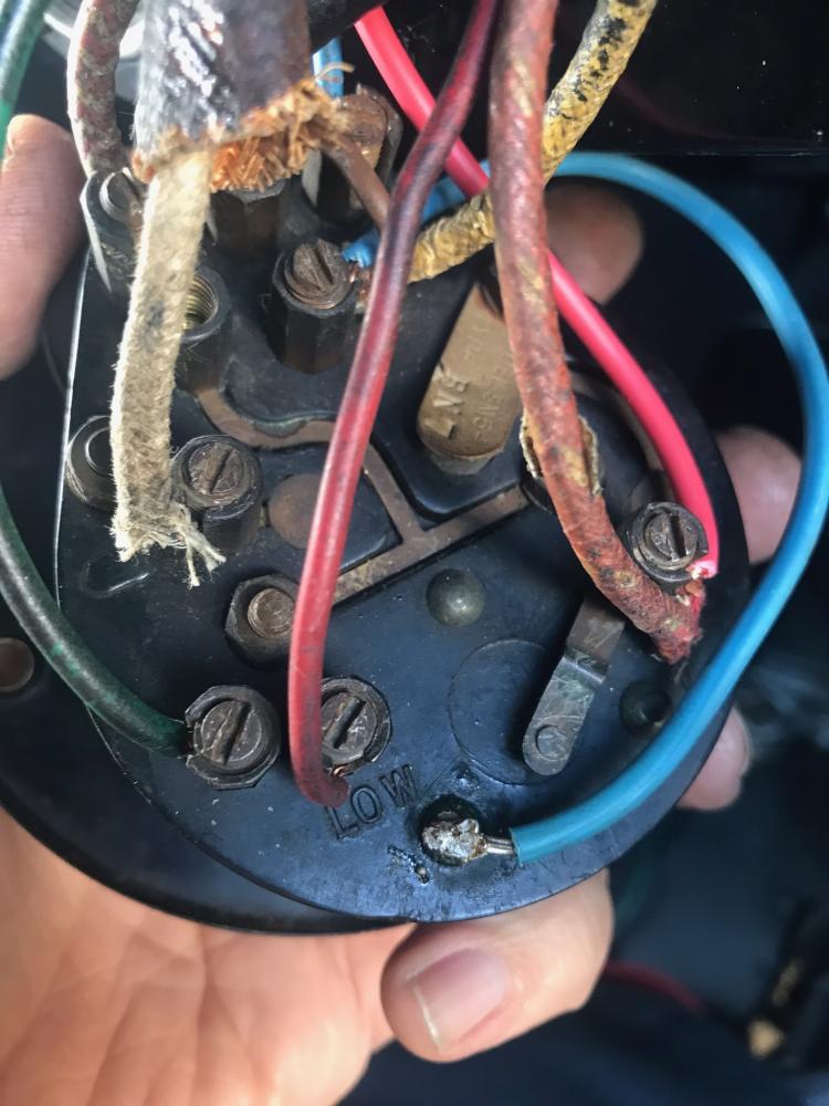
   
Reply
#13
Hi Lowbarn

The 'shell' of the warning lamp holder connects to the three rivets. The uppermost rivet connects to an internal brass strip which runs vertically up to the central internal contact for the cam switches that select High/Low charge. This central cam switch contact also connects directly through to the external +D terminal.

If the brass strip was O/C the added blue wire would effect a cure, but removing it would prevent the lamp from illuminating.

Another possibility is that the through connection from the central cam switch contact to the external +D terminal has failed, and the blue wire is to cure this. In this situation, removing the blue wire will effectively connect the warning lamp between +D and F when High charge is called for. There may be enough voltage difference between +D and F to illuminate it. The dynamo will always be in the Low charge state regardless of switch setting, assuming it has a functioning Low charge resistor.

I have a half finished schematic for this, If I get time I will PM it to you.
Reply
#14
(28-03-2023, 07:44 AM)Lowbarn Wrote: This is a photo of the rear of the switch. 
Someone has added an extra wire (blue) soldered near to the ignition light  from the D terminal. Disconnecting it causes the ignition light to stay on continuously. 
Is this a fix for broken switch internals?

Looks like a fix for the common problem of the switch panel's metal track to the ignition warning lamp having snapped. You can just see the break on this 'work in progress' switch panel I was restoring a few years ago. I just soldered a piece of copper wire across the break.

[Image: 49983752958_9d98125b8e_k.jpg]
Reply
#15
Thanks for those replies gents. I would most likely have been tempted to dismantle the switch to see how it worked, now I can see it’s best to leave well alone.
I don’t think I have found a schematic of the internals of this switch. Several pictures of the external wiring, which is how I noticed that D and F has been reversed.

I’m still focused on getting the dynamo to work reliably, even though we don’t really need it for the journeys we do.

What would be the long term effects on the dynamo if the the D and F wires had been reversed at the switch?
Reply
#16
Good day All
Is it possible to use a diode the Lm 74611 kkt instead of the old cut out relay
Reply
#17
I haven't done it but I only hear good reports on this forum. It's actually a SM74611 smart diode from Texas Instruments. You can buy them online or go to themagnetoguys.co.uk who supply one on a pcb with wires attached.
To be clear, it is a smart diode that detects voltage difference and switches on a FET dropping very little forward voltage. Many people use a normal diode which will drop 0.5-0.6 volts between the dynamo and the other side. This is acceptable but will dissipate more power and therefore need to be heat sinked, you may as well use the smart diode.
Reply
#18
If you haven't removed the dynamo yet, it can be tested as follows. Disconnect the "D" and "F" cables from the dynamo. Use an analogue voltmeter connected between "D and earth". Run the engine and you should get between 1 and 1 1/2 volts reading on the volt meter, this indicates that brushes and dynamo armature are good. Next connect the "D" and "F" terminals together with a short lead. With the voltmeter connected "D" to earth, run the engine, you should get approx' 7 1/2 volts reading on voltmeter. If you get these results, your dynamo is good. Reconnect "D" and "F" to dynamo. Next remove "D" and "F" leads from cut out, link the leads together, connect voltmeter "D" to earth , run engine. If you get 7 1/2 volts the "D" and "F" leads are sound, and the fault is in the cut out or SM5 switch. If you get no voltage for this test, there is a break in the "D" lead. If you get 1-1 1/2 volts, there is a break in the "F" lead.
Reply


Forum Jump:


Users browsing this thread: 5 Guest(s)