Austin Seven Differential Adjusting Tools (as per factory)

Tool No. XLW 1102
Source - The Austin Seven Source Book
by Bryan Purves
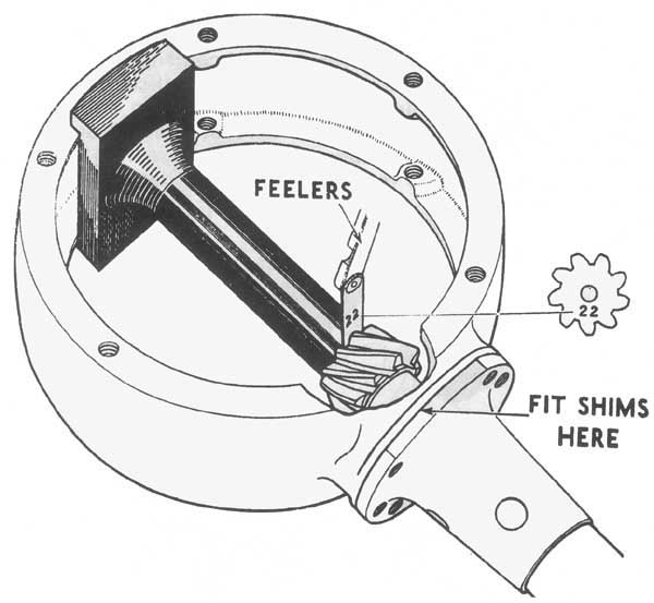
The 'D' type axle bevel pinion could be quickly located in its correct position relative to the crown wheel. The gauge was placed in the axle casing bearing housing and rotated until the scale reading corresponded to the number etched on the bevel pinion flange. Shims were then inserted to secure the bevel pinion in position with the bevel pinion end face tight up against the gauge.

Bevel Pinion Meshing Gauges
Toot No. XLW 580
Source - The Austin Seven Source Book
by Bryan Purves
The last process in the manufacture of bevels was the mating together and running-in of each pair of wheels on a special machine, part of the duty of which was to indicate the correct distance from the ground end of the pinion to the centre line of the axle shafts. The distance varied from gear to gear and a number was etched on the bolting-up face of every crown wheel and on the end face of every bevel pinion as a reference for gauging when fitting the mating pinion. The gauge was designed for use on axle types up to when the 'D' type axle was introduced. The first operation was to assemble the bevel pinion shaft into the torque tube. The torque assembly was then offered up to the axle case with no shims fitted between the torque tube flange and the case. The gauge was then placed against the register in the axle case in order that the small end came against the end of the pinion. Feelers were then inserted to the value of the figure etched on the pinion end face between the gauge and pinion.

An example of the value, in this case 20, etched on the pinion end face
photograph by Bruce White
The torque tube was then pressed down towards the gauge and appropriate shims selected which just filled the space between the torque tube and axle case flanges. The torque tube assembly was then bolted up being in the correct position from the centre line of the axle shaft, for the crown wheel to be brought into correct mesh. With reference to the threaded torque tube axle, adjustment of the pinion was effected by the same procedure with the exception that in place of fitting shims the torque tube assembly was screwed into the axle case until the correct position according to the gauge and feelers was found. In this type of axle the pinion could not be assembled into the torque tube away from the axle.